Last week’s adventures ended in the machining of a successful replacement hub blank for the Fries Ultra 70 IMAX format camera. This week, I machined the required features onto the hub blank so the flywheel could be permanently mounted to the movement and timed correctly to the shutter drive. The process was straightforward, if a bit tedious due to the precision required. I suspect that the original flywheel assembly failed because the flywheel itself is very heavy and was not properly balanced; and the main drive shaft it was attached to was not robust enough to handle the stress and inertia of the camera’s start and stop cycles. One of the main concerns in this repair is to make sure that whatever I add to the hub is as symmetrical and balanced as possible, so all the screws, pins, nuts, bolts, etc. were installed in matched pairs. Here was my process:
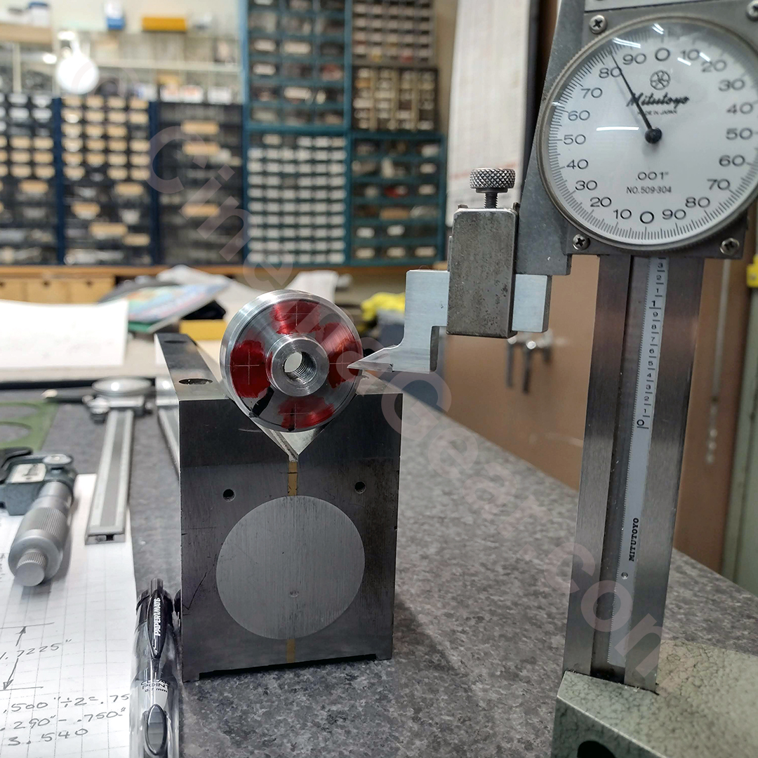
- I layed out where all of the screws and dowel pins were going to go on the hub blank that I machined last week. An amazingly time consuming process.
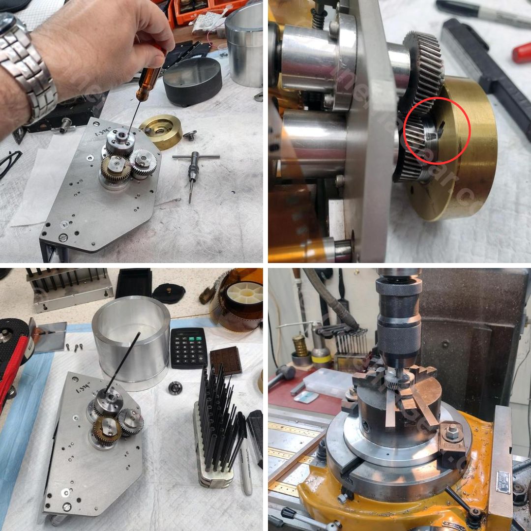
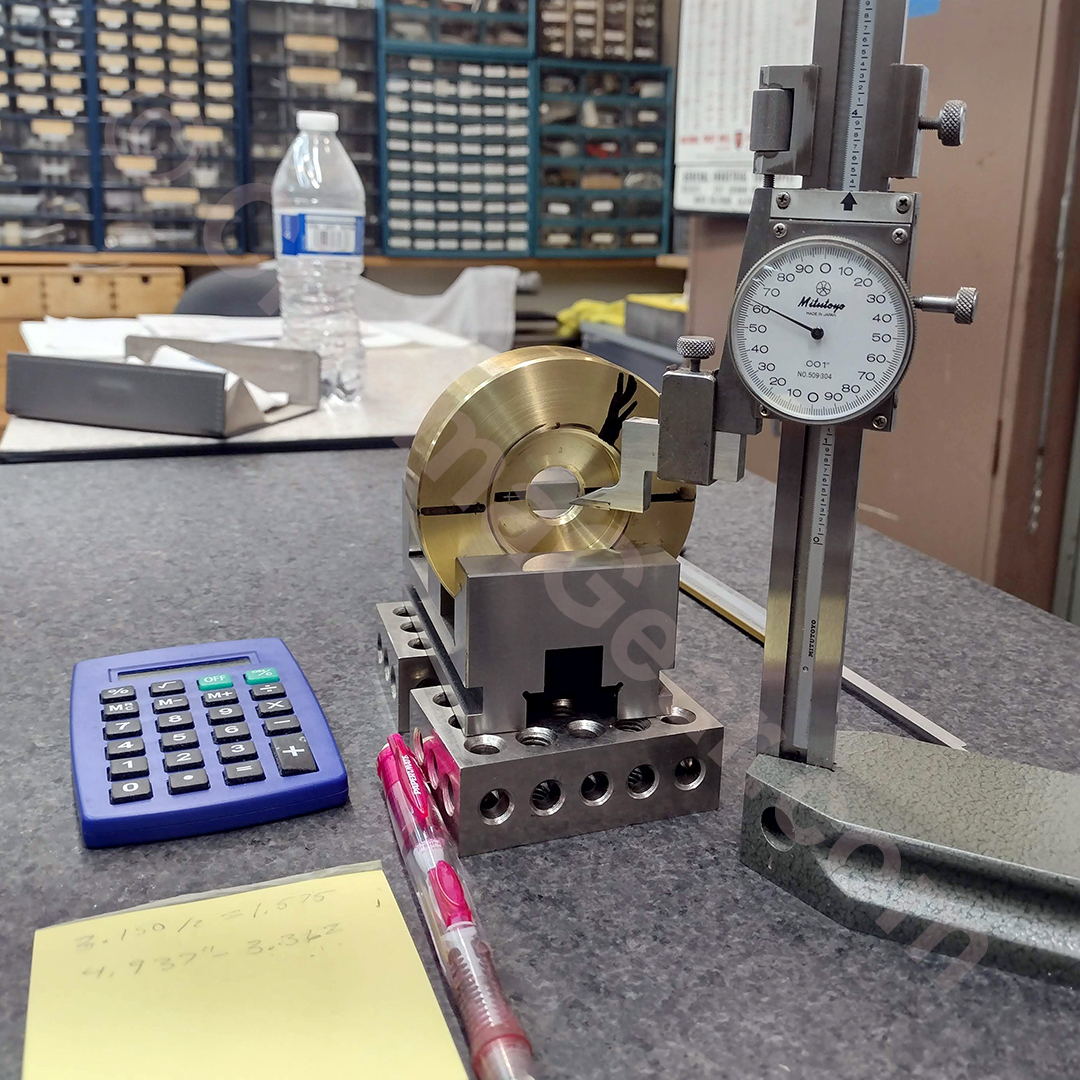
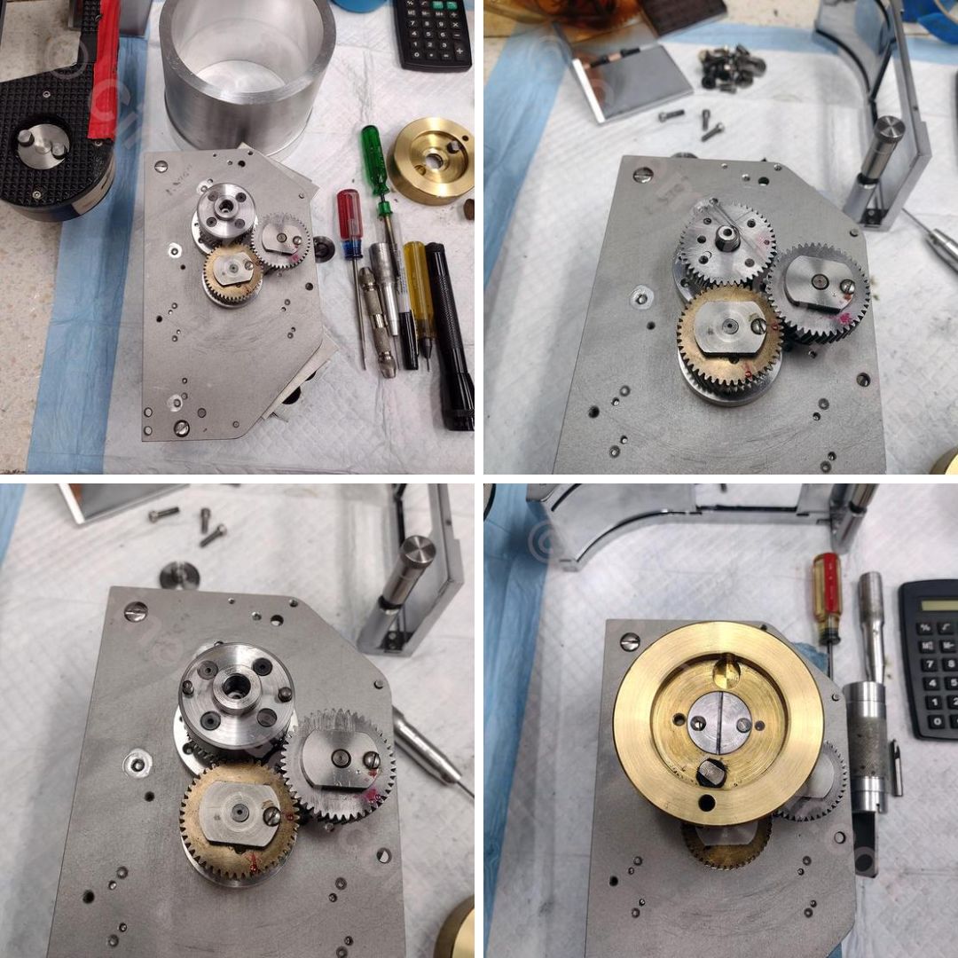
- The hub was mounted on a turntable on the milling machine, indicated for center, and 3 of 4 holes for screws to attach the hub to the pull-down claw timing gear were located, clearance drilled, and countersunk. One of the 4 holes was drilled and tapped for a set screw so that, when the hub is threaded onto the movement drive shaft, the hub can be temporarily locked in place so that timing between the movement and the shutter can be established. Once timing was established, that hole was drilled and countersunk as well so the hub was permanently attached to the pull-down claw timing gear.
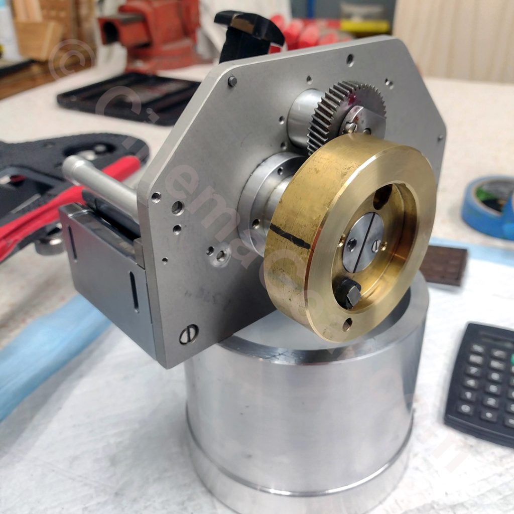
- The flywheel couples with a hub that drives the shutter mechanism. The flywheel and the shutter drive hub are keyed to each other so the movement and shutter drive are always in time. The problem to solve here is to return the flywheel to its original position so the film transport and shutter are brought back into sync. I threaded the hub onto the main drive shaft and locked it in place with the set screw. Then I installed the flywheel and temporarily held it in place with the flywheel retaining screw I made last week. I estimated the relationship between the flywheel and the movement, then reinstalled the movement in the camera. I checked the timing between the shutter and the film transport, and then repeated that process until I had established timing. Once timing was re-established, I made a temporary timing mark with a Sharpie on the flywheel, the hub, and the pull-down claw timing gear. Then I removed the flywheel, transferred the holes from the hub to the timing gear, put the timing gear on the milling machine using the same setup I used to drill the holes in the hub, and then spotted, drilled and tapped holes in the pull-down claw timing gear that match the holes in the hub.
- With the hub’s permanent position established, I drilled and countersunk the 4th hole and installed the hub onto the pull-down claw timing gear.
- Originally, the flywheel was keyed to the drive shaft. To ensure the flywheel was always mounted to the movement correctly, I chose to use two different size dowel pins that went between the flywheel and the hub instead of a keyway. This would ensure the flywheel can only be attached the correct way. The final thing I had time to do this week was to drill, ream, and install the two dowel pins. Or, at least, I thought it was the final thing, until I noticed that the little flathead screw that keeps the flywheel retaining screw locked in place was positioned incorrectly, so a new hole had to be drilled.
Next week, I have to static balance the flywheel, and hopefully will get to test the camera under power.