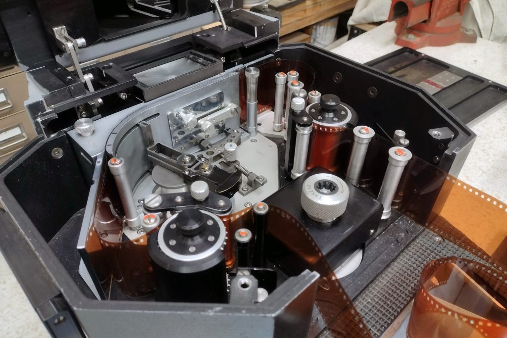
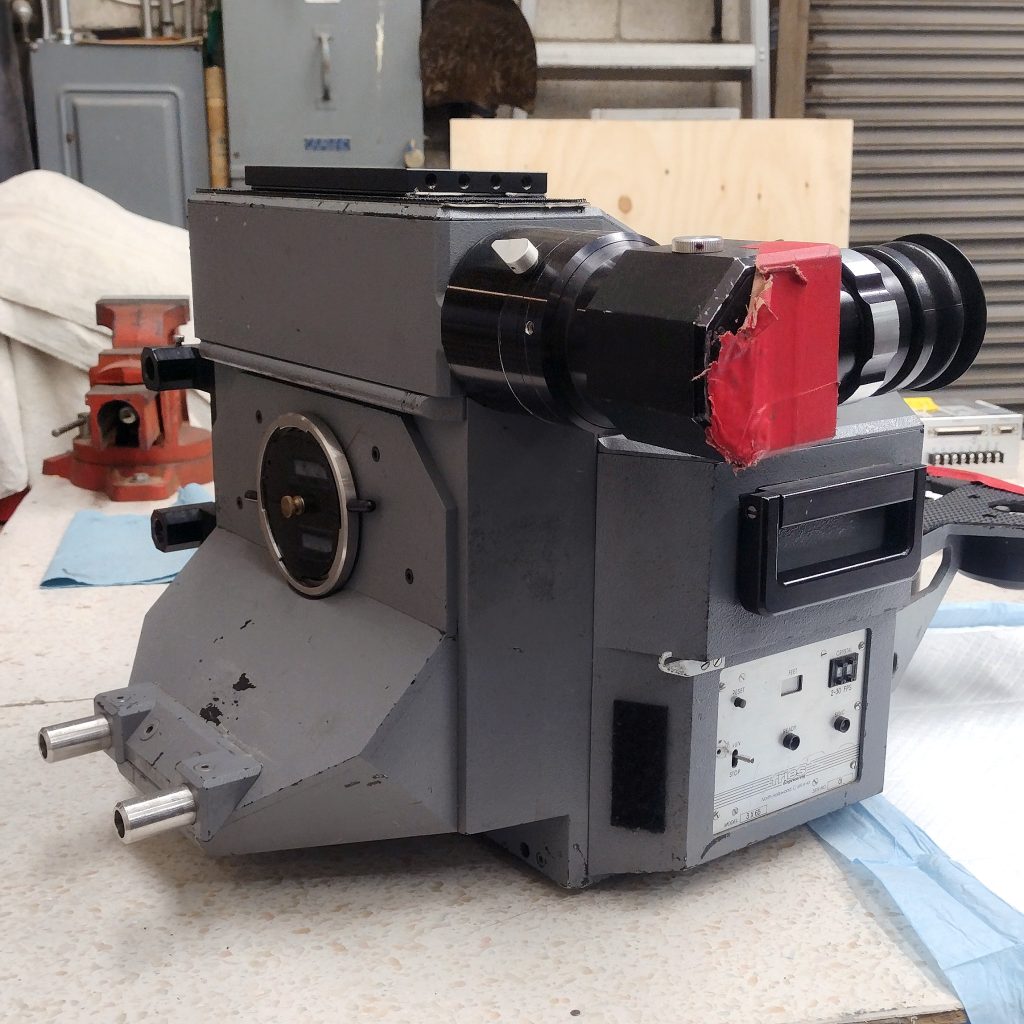
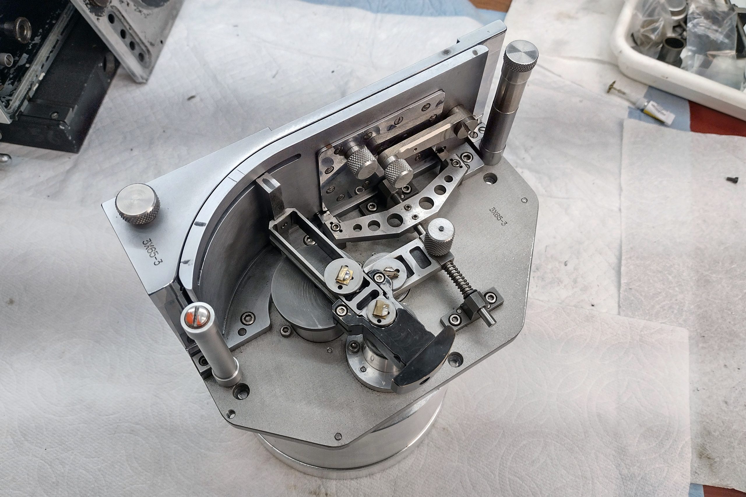
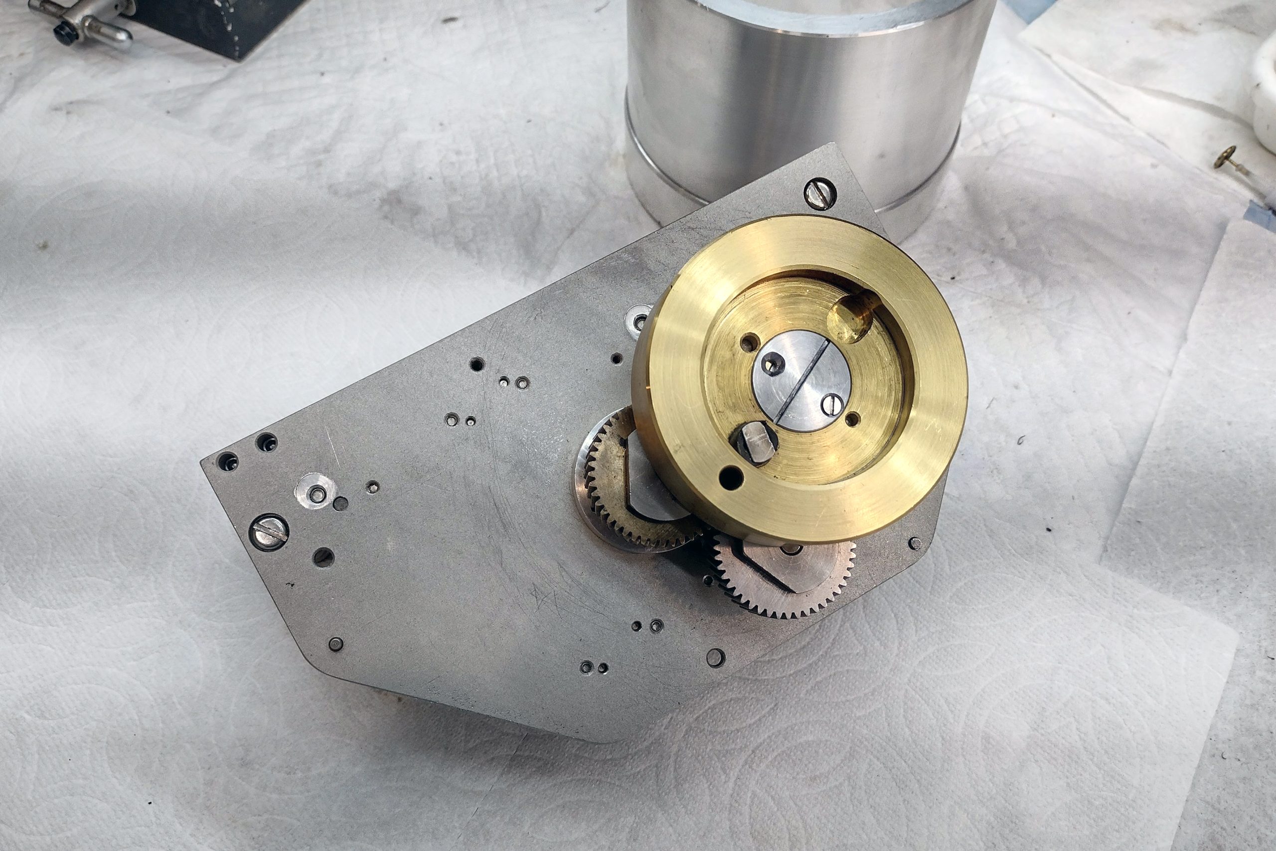
And so we come to the end of my project repairing the Fries Engineering Ultra 70 3×65 IMAX-format camera. This project was quite challenging. Coming up with retrofit parts that would preserve the function and integrity of the movement, but still be serviceable in the future, required a lot of careful thought and planning. Because the main drive shaft was sheared off and not repairable, it seemed that I could use the timing gears that hold the pull-down claw and registration pin in sync as a platform to mount the retrofit parts on the movement. The challenge was to make them small and light enough, and to maintain the spacing between the movement and the mirrored shutter drive mechanism so that all could work together properly. After you read the details of the final phase of this project described below, you will find a video detailing the steps taken in the final stage and showing the camera running again at long last.
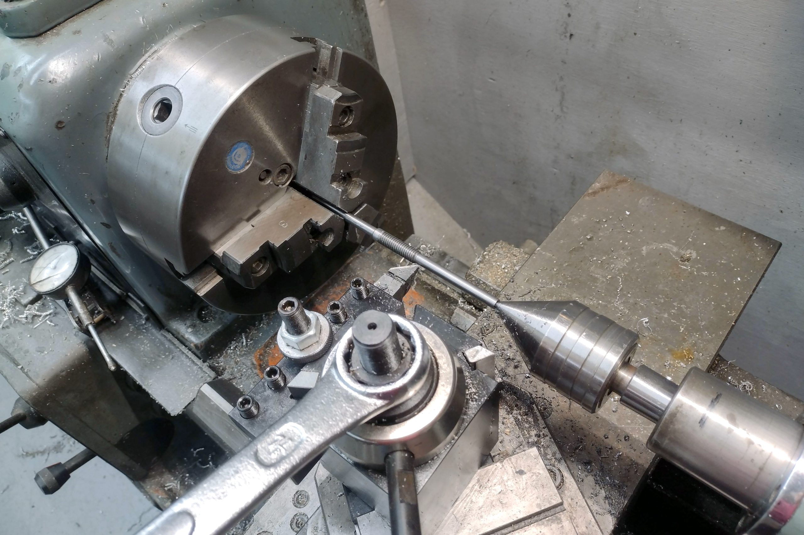
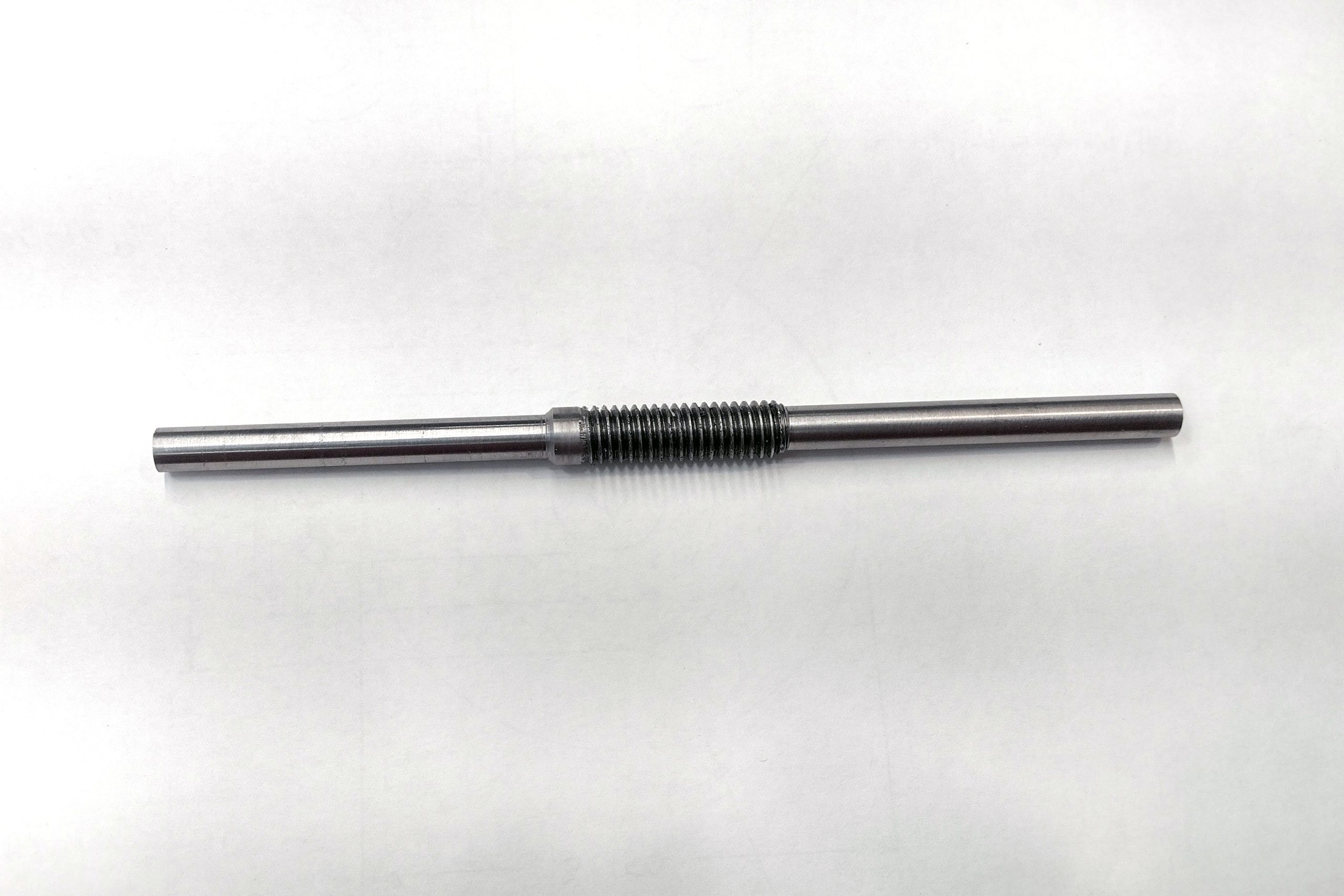
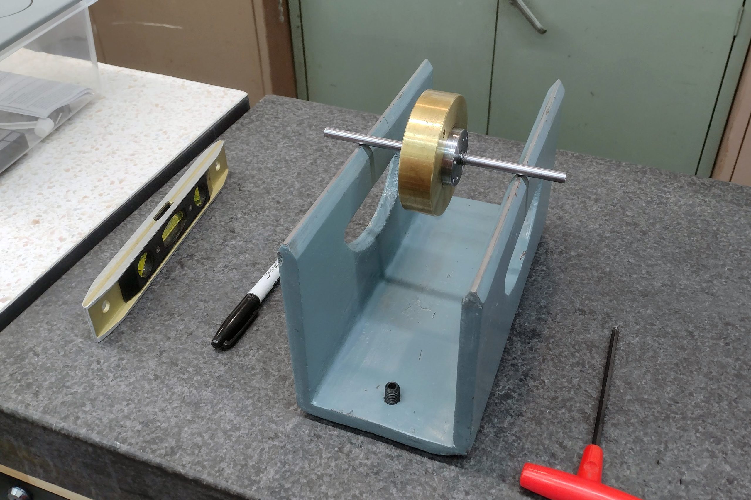
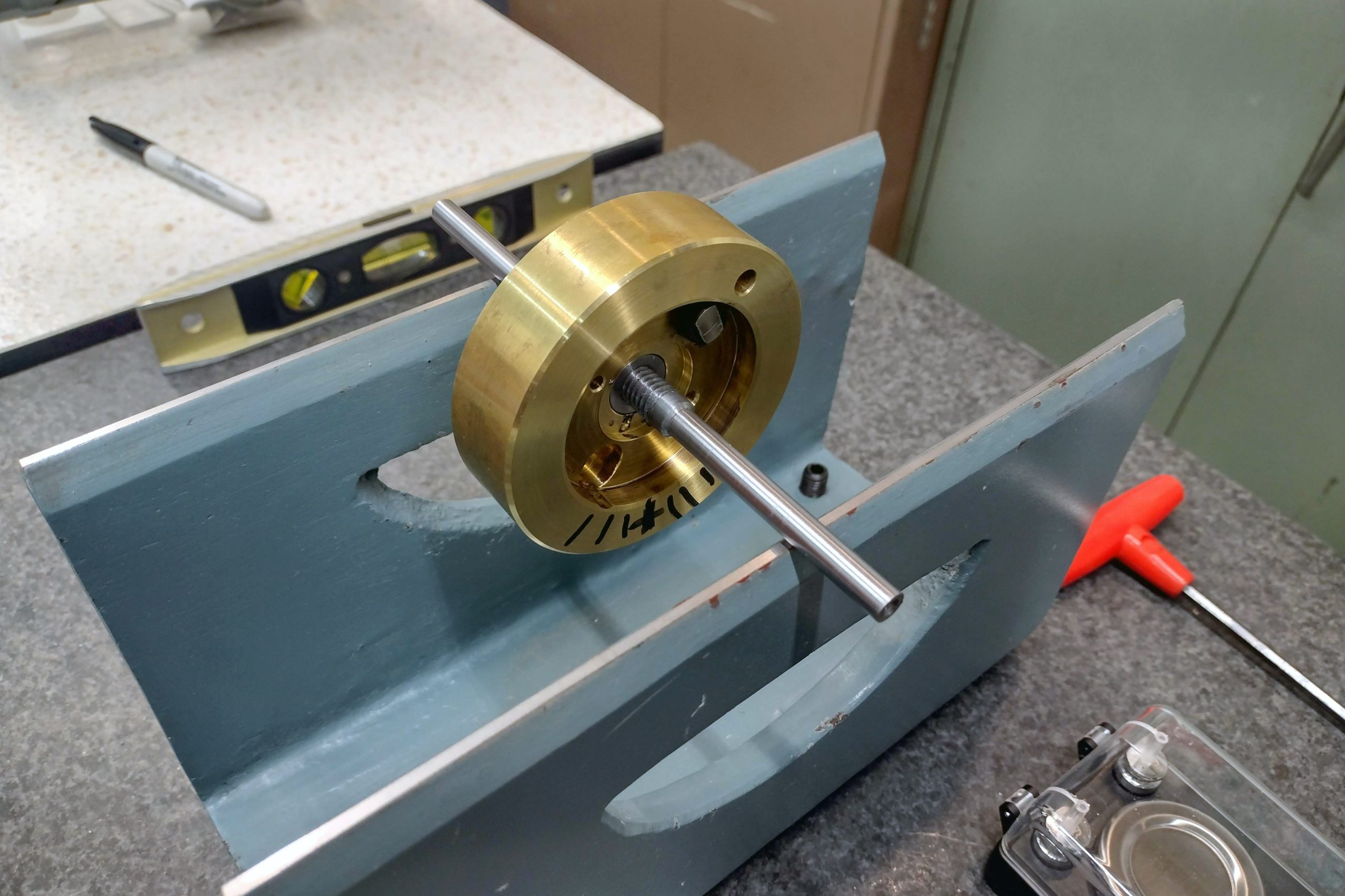
As promised last week, this week I spent many, many hours setting up and balancing the flywheel in the Fries Ultra 70 (3×65) IMAX format camera. I don’t have any way to dynamically balance the flywheel, so I thought I would start the process by static balancing it and see how that worked. Anyone who’s done this knows how tedious a process it is. So, once again, and hoping it was for the last time, I took the movement out of the camera and removed the flywheel. I then had to make an arbor so that I could mount the flywheel on the balancing rig. Because I added such a big, bulky hub to the flywheel, I thought it was necessary to balance the flywheel and the hub together. That meant I had to machine the arbor to mate with the new hub. After numerous hours of machining, polishing, threading, and measuring, I had an arbor that was parallel and accurate to within 0.0003”.
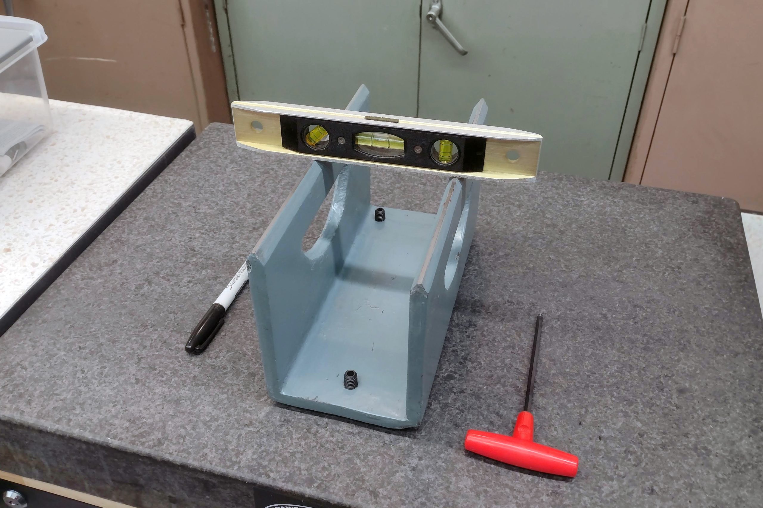
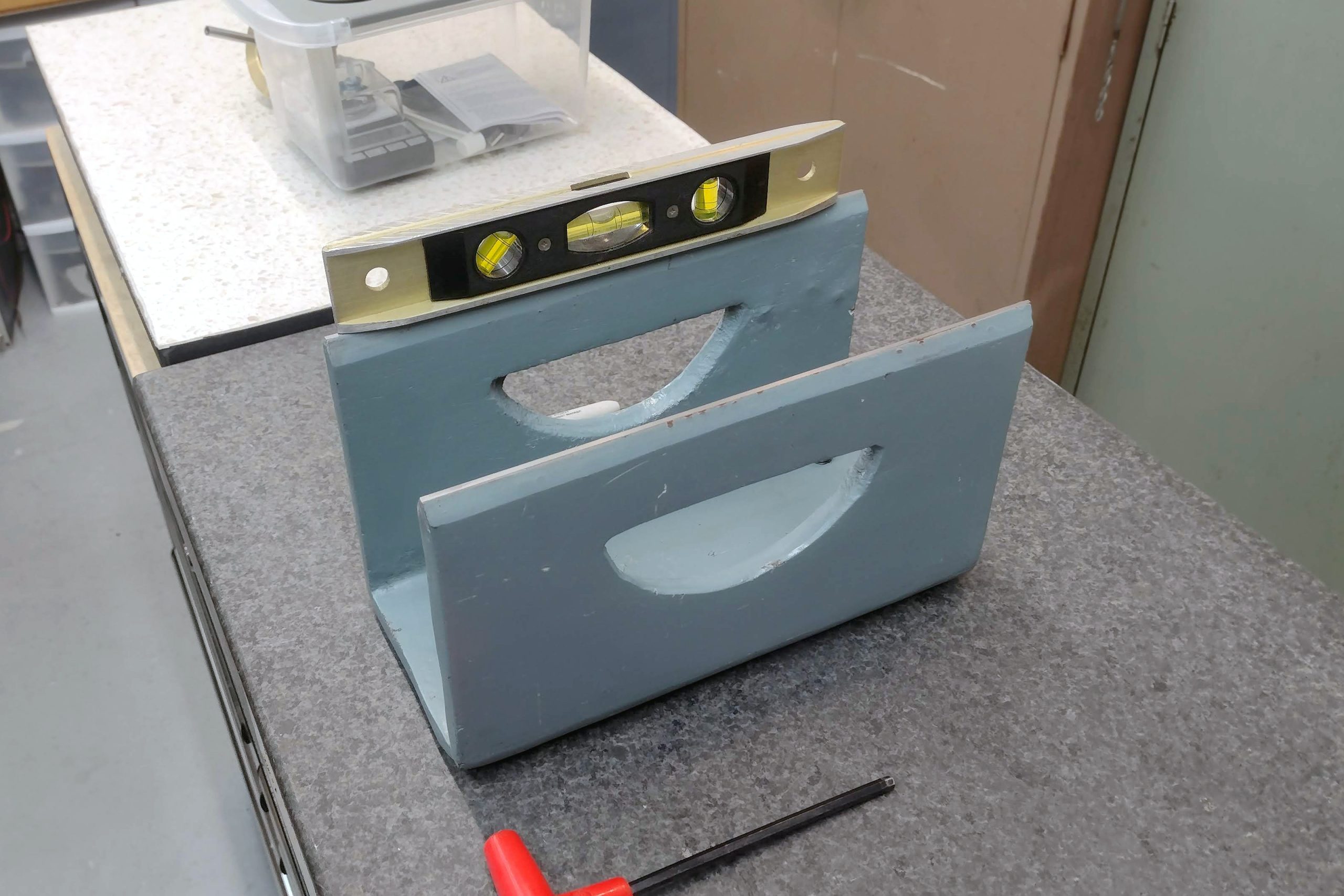
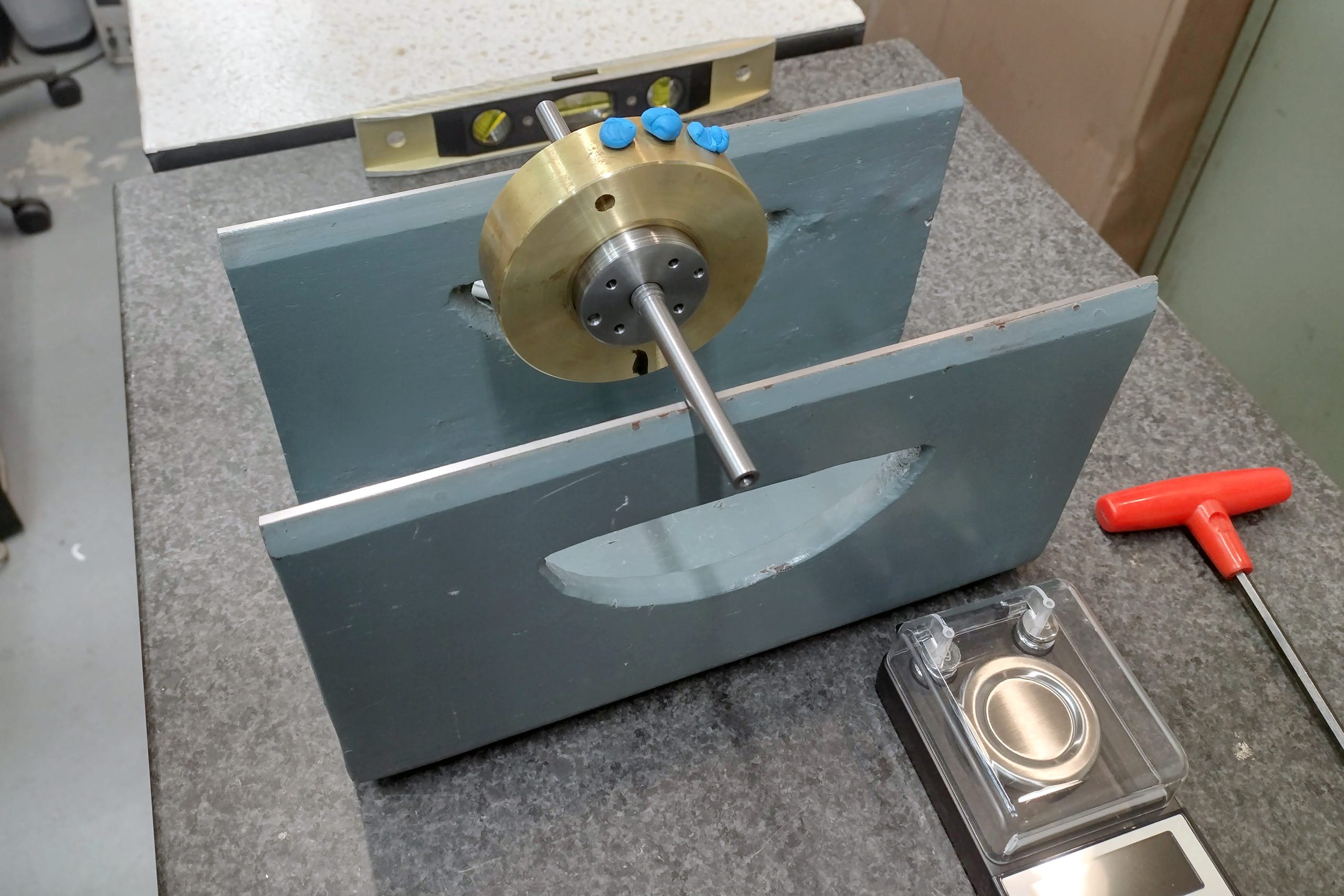
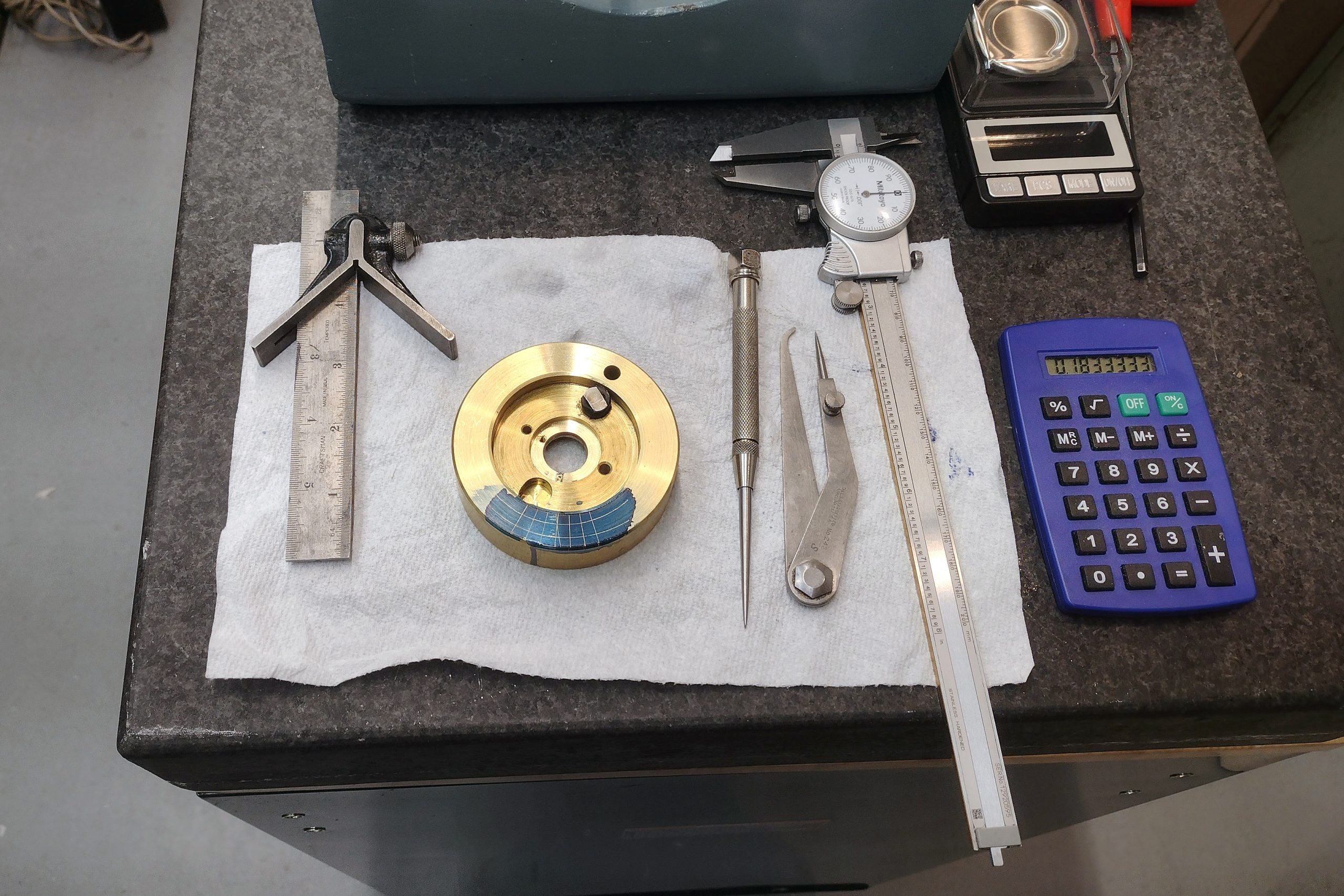
The next step was to find my balancing rig, set it up on the granite plate, and level it. The object of this balancing exercise is to ensure that, with the flywheel mounted on the arbor and installed on the balancing rig, that no matter what position you put the flywheel in, it simply stays in that position and doesn’t roll down to a heavy spot. The balancing rig has to be level in both directions in order for this process to work. Somehow, in my move, I lost my Starrett precision level, so I struggled along with this handy torpedo level to get everything leveled as close as possible. I mounted the flywheel on the new arbor, set it up on the ground and polished knife edges of the balancing rig, and began marking where the heavy spots were.
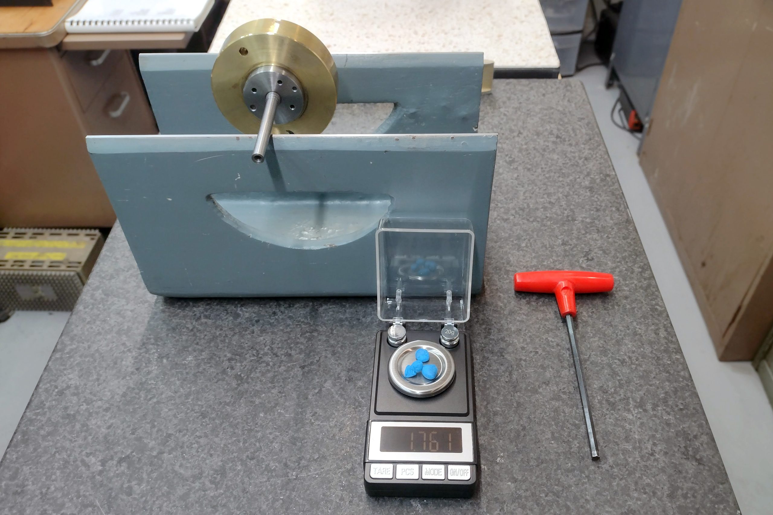
The addition of the new hub, machining away some of the material from the original hub, and the off-center weight of the Fries coupling, made balancing this flywheel a challenge to say the least. I like to have a visual reference to give me some idea of just how much material I’m going to end up removing from whatever I am trying to balance. So the first step in my process is to see where the heavy spot on the flywheel is, mark that with a Sharpie, and stick bits of clay opposite of the heavy spot. Once I had a reasonable balance where the flywheel would stay in place no matter where I put it, I weighed the clay so I had an idea in my head of how much material I would need to remove.
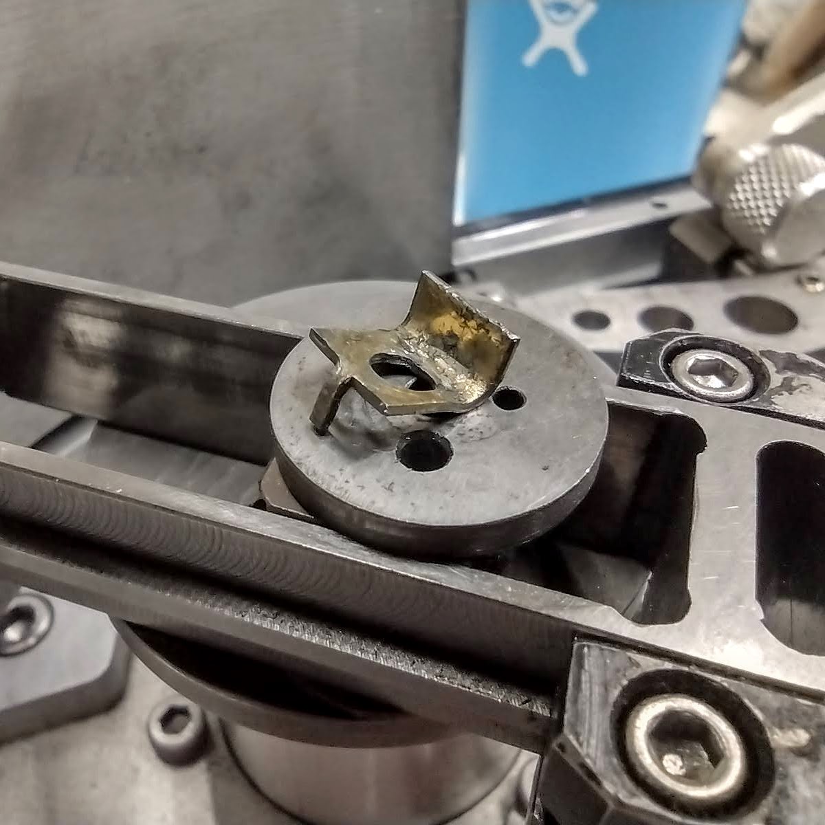
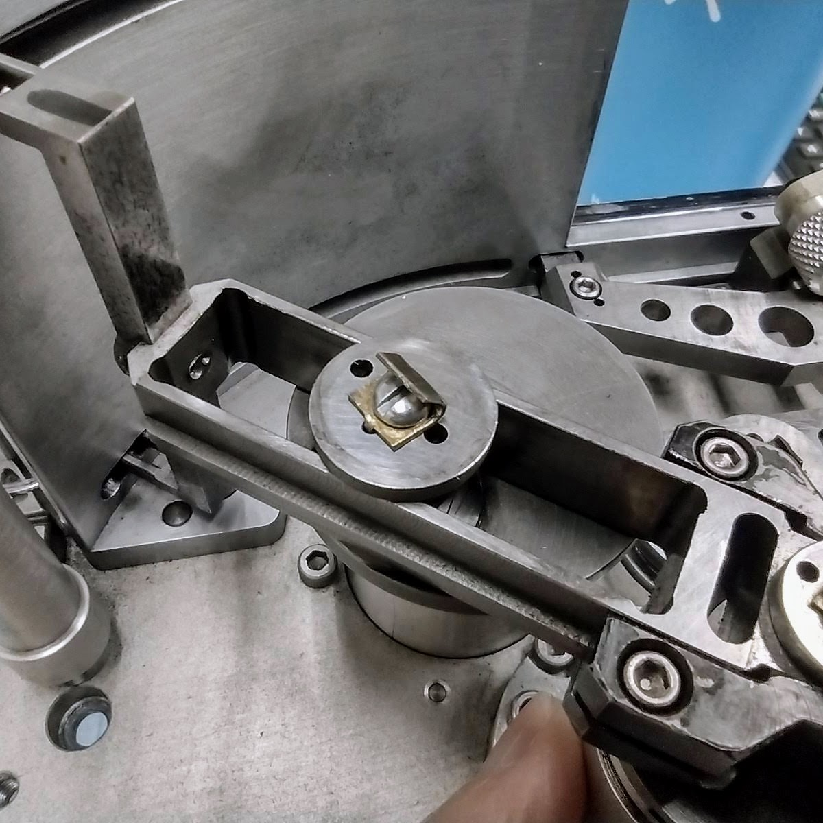
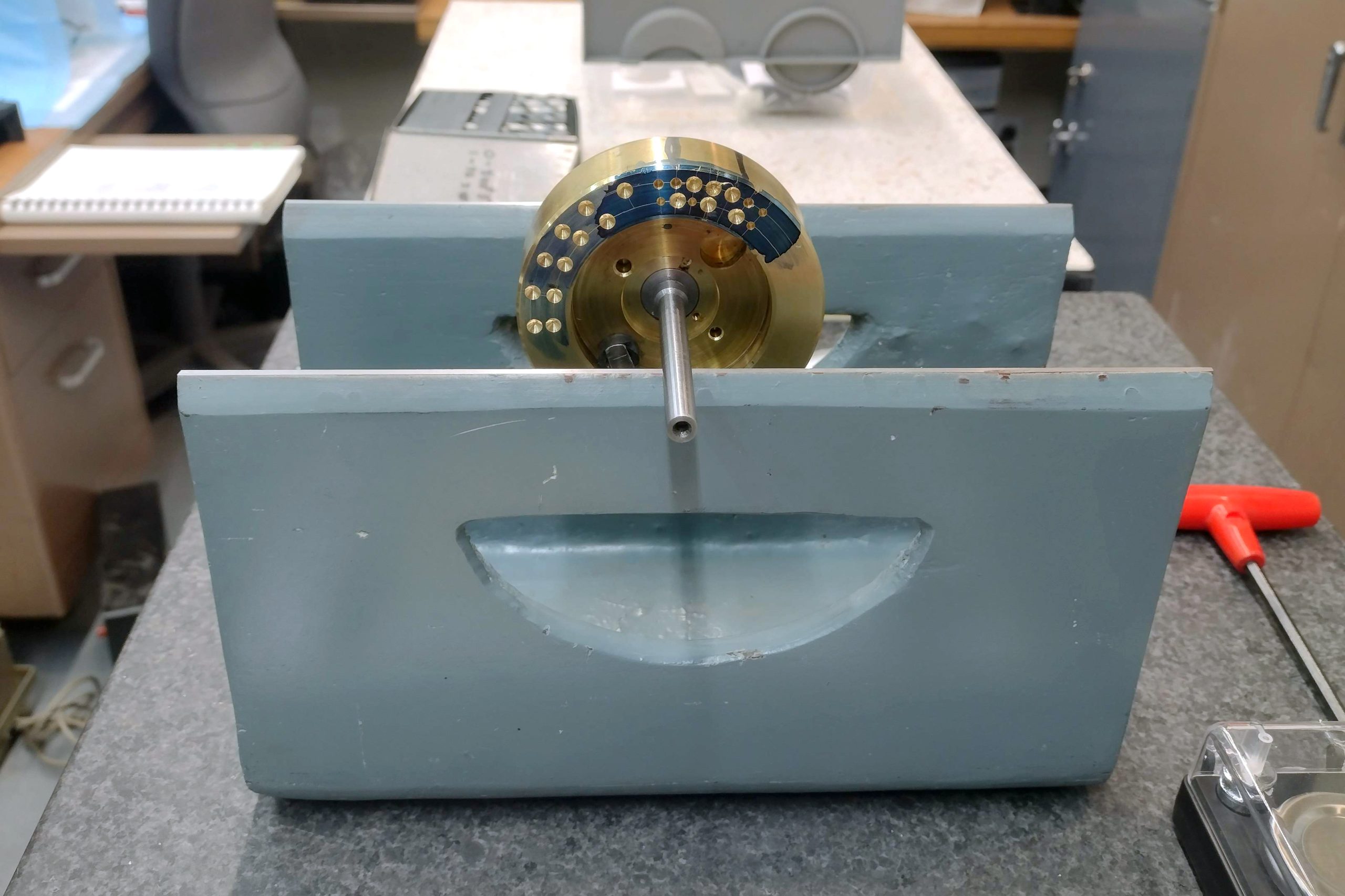
I layed out a drill pattern on the flywheel and started the long, tedious process of drilling out a little bit, testing, drilling out a little bit, testing, etcetera, over and over, until the flywheel was balanced at last. At that point, I cleaned all of the marks off of the flywheel, reinstalled it on the movement, and reinstalled the movement in the camera. Then I carefully inspected and lubricated all the moving parts. While I was doing this, I discovered that one of the brass locking tabs that holds a thrust washer on the pull-down claw was not installed correctly, so that had to be repaired. Confident now that all of the moving surfaces were lubricated, it was time to run the camera.
Then, the moment of truth. Would the camera run? I hooked up my power supply, figured out what the correct pin outs for the power cable are, turned on the power supply, the torque motor started, and then … nothing. After a brief search, I realized that the buckle trips were both tripped. After they were reset, victory! I have only run film by hand through the camera, but I have tested it under power at 5 fps, 10 fps, 20 fps, and 24 fps, and while it makes a lot of noise, it runs really well. I think it is fixed! https://cinemagear.com/blog/tag/fries/
Presented here is a short video detailing the last few steps to get the camera running again, along with my initial test of the camera running by hand and under power.