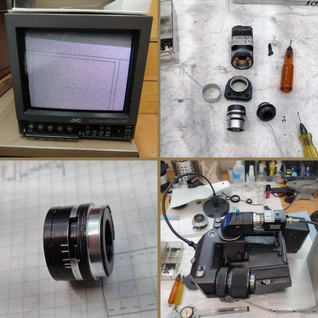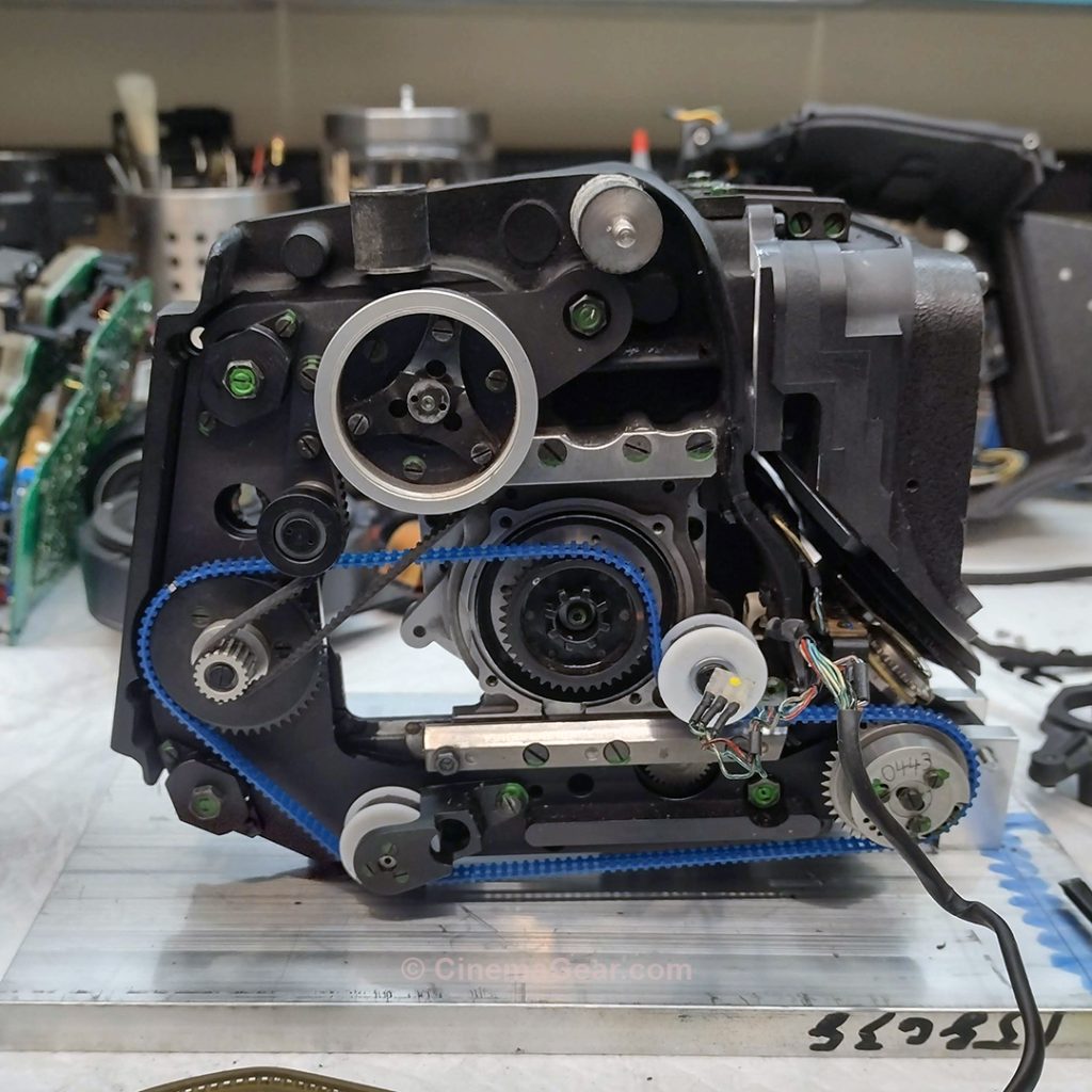
A few weeks ago, a dear friend of mine called with a slight amount of panic in his voice to tell me his venerable Arri 35 BL 4S had stopped working. After a little detective work over the phone, we concluded that the problem was likely with the drive belts, an unfortunately common problem with the 35 BL cameras. Currently, I am not taking much outside work in, but I couldn’t turn my friend away and thought it would be a simple fix. As those who have faced this problem before know, these belts have become very hard to find and very expensive. This is a repair I have not done for more than a dozen years, but I remember hearing that belts made by Pic Design would work in this application. Consensus was that the Pic belts might be a little bit noisier, but not significantly. My friend found several videos on YouTube showing this replacement, and that opinion seems to be correct. So he ordered the belts from Pic and, after waiting a very long time to get them in, the belts finally arrived and I began the repairs.
My re-learning curve after having not worked on a BL for many years was high, but it came back to me as I was going along. As I never thought I would see the inside of a BL again, I had given my two fixture plates away, so I had to remake those before I could begin disassembly. The most tedious part of the repair was finding all of the screws that hold the camera case together, then numbering and labeling all of the isolation mounts and their matching shims, finding quite a few hidden screws, and finally getting the camera out of its housing.
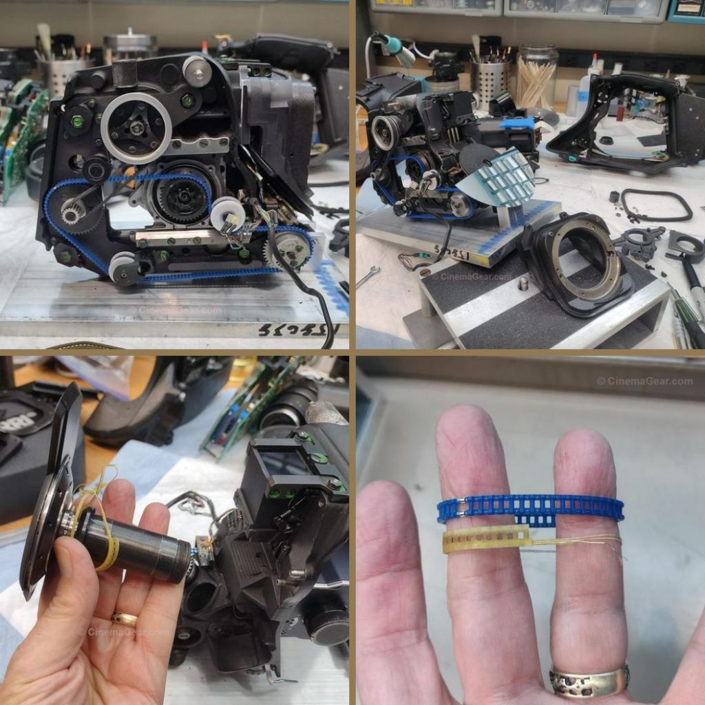
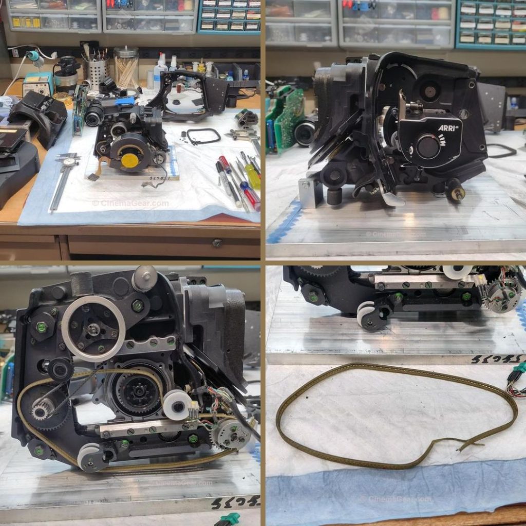
The main drive belt is relatively simple to replace, but there is a secondary belt that drives the shutter, and that requires taking the shutter assembly out of the camera. In order to remove the shutter, you must first remove the lens board. Then the shutter assembly can be removed from the midrib and whatever is left of the old belt can be cleaned out and the new belt installed. With the belts replaced and the shutter reinstalled, the next operation was to time the shutter to the film transport. There are a couple of processes that have to be timed once all of the parts are in place: the shutter has to be fully closed when the film is moving and the main motor has to be timed so that, when the camera is turned off, the shutter stops at top dead center in the viewfinding position. With all of that accomplished, I began the process of reassembling the camera into its housing.
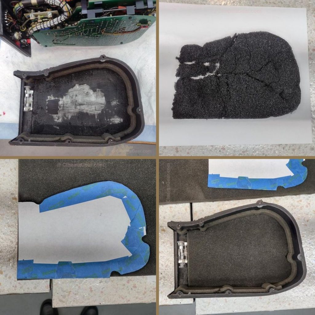
As I was reassembling the camera, I noticed that the insulating foam on the inside of the motor cover had rotted away, so I stripped that out, made a cardboard pattern, cut a new piece of foam, and installed it in the motor cover. With everything now fully reassembled, I checked the camera under power and used a strobe light to make sure it was truly running at 24 frames per second. As a triple check before I reinstalled the PL lens mount, I checked to make sure the shutter and film transport were in time, and that the shutter was stopped in the top dead center viewfinding position. With that confirmed, I reinstalled the PL mount and checked and adjusted the flange focal depth.
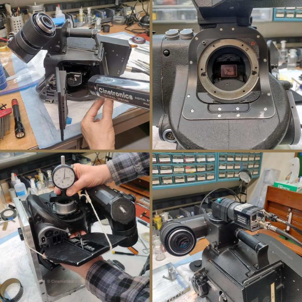
At this point, the camera was running, everything was back in its correct place, and I thought I was finished. Then I noticed that the video tap camera was sitting at a strange angle. Sure enough, it was broken. Despite the fact that there is a label on it that says “Not a handle”, clearly someone had picked up the camera by the video tap. This had broken the internal optical components that relay the image to the video camera, as you can see in the photos. They were damaged beyond repair, so I am in the process of making replacement parts. The repair will continue next week.