You might remember this Fries 3×65 IMAX format camera from the repairs I did on the movement last spring. The owner brought to my attention that people who have shot with this camera in the past were concerned with the way the pull-down claw and registration pin assemblies were held in place. Their feeling was that they were not secure enough to prevent sprocket hole or film damage. I was asked to come up with a better method of retaining the pull-down claw and the registration pin to their cams. The original design of this movement took inspiration from the Mitchell Standard or GC high speed movements, where the thrust bearings were held in place by a square-headed screw that was retained by a brass locking tab.
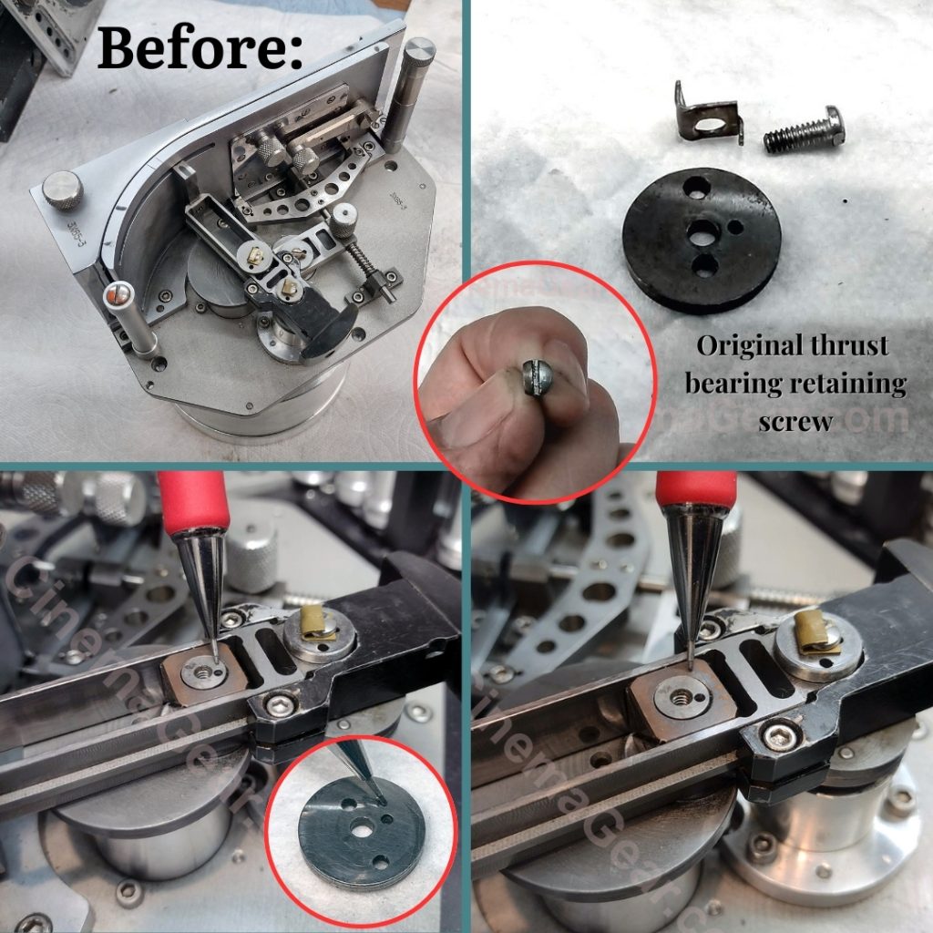
The locking tab has three main surfaces: a key that goes through a hole in the thrust washer and into a hole in the cam; a flat main body with a hole in the middle that the square-headed screw fits through; and a shoulder that is folded up to form the locking tab against a flat face of the square-headed screw. Whoever did this work originally chose to take a 4-40 pan-head screw and flatten off one face of it for the locking tab. This was not adequate to keep everything in place and registered.

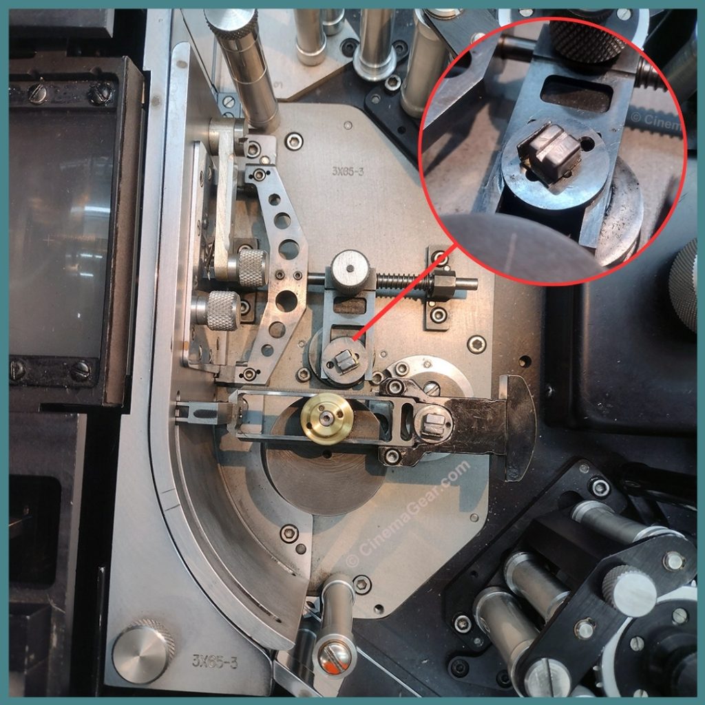
As I dug into this further, I discovered that the hole in the pull-down claw main thrust washer didn’t line up with the hole in the cam, so the locking tab in this position couldn’t do its job. This created another problem because I couldn’t simply replace the original screw with a square-headed screw because the locking tab could only go through the thrust washer, but could not lock to the cam. And so I had to come up with a whole new approach in order to fix this.
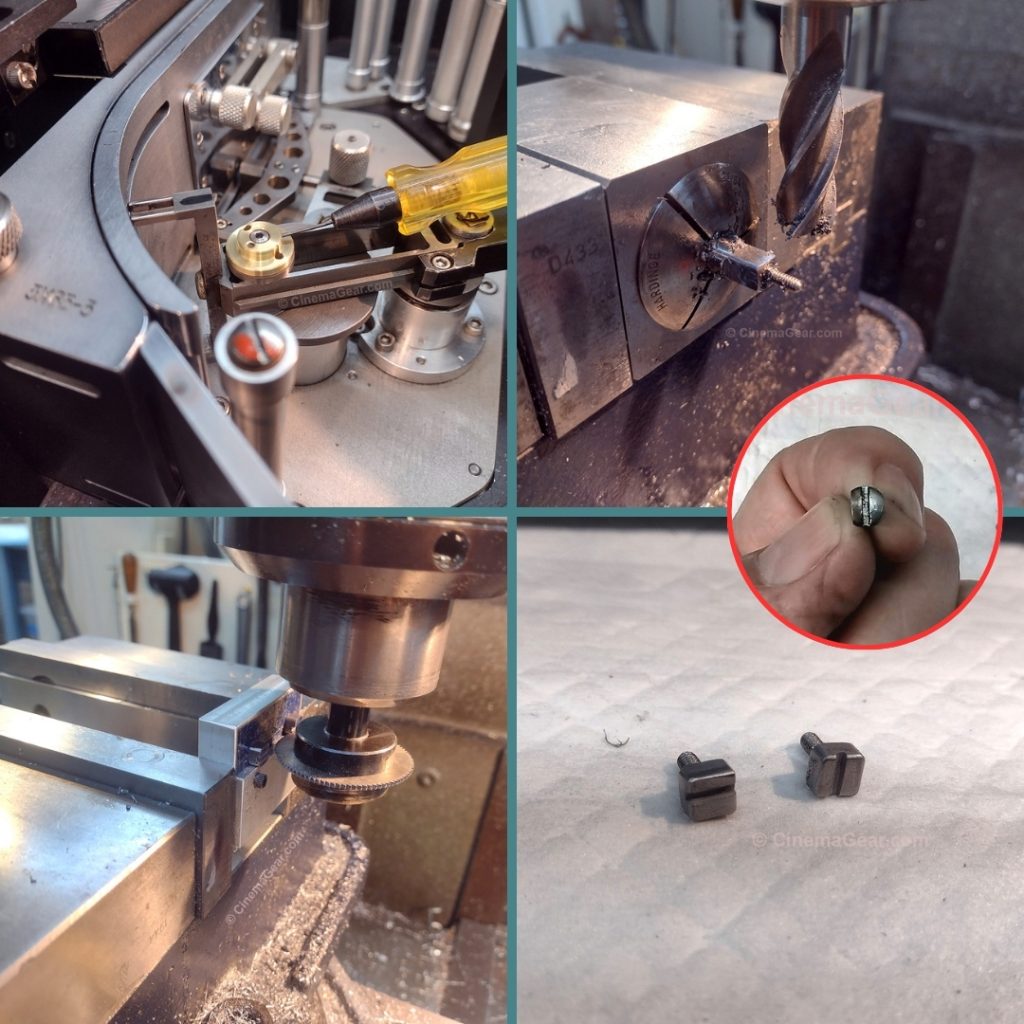
I noticed that the camshaft was slightly raised above the bearing block that operates the pull-down claw. This meant I should be able to squeeze the thrust bearing against the camshaft, provided I could keep the thrust washer from turning and loosening as the pull-down claw went through its cycle. I installed a dowel pin in the original thrust washer and machined a brass bearing that would replace the original screw and locking tab. The new bearing sandwiches the thrust bearing against the cam. The dowel pin goes through a hole in the new bearing to act as a locking pin.
The new bearing also has a raised portion that a socket head cap screw goes through to hold the thrust bearing in place, and a set screw that goes through the side of the raised portion to lock the socket head cap screw in place so that the socket head cap screw won’t back off while the movement is operating. Fortunately, the other two places where there are thrust washers for the registration pin and pull-down assemblies, all the holes lined up properly, so the original square-headed screw and locking tab concept could be used there. Back to the lathe and mill, I machined two replacement square-headed screws, installed everything, and voila! A working movement! In theory. Testing still to come.